Pic16f628a Programmer Circuit

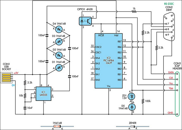
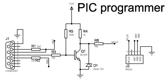
PIC Programmer Circuit diagram Following uJDM PIC programmer circuit is a circuit which suitable to do simple pic16f84, pic16f84A, 16c84, 16f628 group. Jan 23, 2016 - This is also an EEPROM programmer as it supports 12Cxx EEPROM. The main component of this PIC microcontroller programming circuit is a.
Introduction This neat little circuit provides 8 LEDs directly driven from the PIC along with a single mode control switch. The firmware elsewhere on this page drives the LEDs with a 5 bit PWM signal providing each of the 8 LED channels with four levels of intensity; off, dim, mid, bright. A number of sequences are programmed into the firmware to provide some interesting visual effects and chase sequences, including the classic effect seen on the car in the Knight Rider TV series (Original Source - ). This is for mostly all of the people here, If you can't SEEEEEEEEEEEEEEEEEEEEEEEEEE at the top of the page are all of the downloads that you need and have the KNOW HOW that you need a programming circuit which is not given here and a programming software that you will need to open the files so that you actually programme the ic (in this case the PIC16F628A) THEN my dears, please don't attempt to build this, cause you are to freakin dumb for that!!!!!!!!!!!!!! Admin/s sorry for me being so straight forward.
Here’s another breadboard module that carries a PIC16F628A microcontroller. The power supply pins and the I/O ports of the PIC16F628A microcontroller are accessed through male headers. It can be easily plugged into a breadboard and is very useful for quick prototyping.
Adobe acrobat xi pro crack xforce autocad. It frees up a lot of space on the breadboard since the oscillator, reset, and ICSP circuits are already built on the module. It is different from the previous in the way that the microcontroller now runs with an external 4.0 MHz crystal. So, this module will be more appropriate for experiments that require accurate timing calculations.

Besides, the PIC16F628a microcontroller allows you to read/write 8-bit data directly through PORTB, which is 8-bit wide (none of the ports in PIC16F688 were 8-bit wide). The layout and the circuit diagram of the module is shown below. The module has ICSP header pins for in-circuit programming, a reset switch, and an LED as power-on indicator. It provides easy access to all the pins of PORTB, and RA0 through RA4 pins of PORTA. Pins RA6 and RA7 are used for external crystal connections, whereas RA5 is input only pin and is used for reset circuit.